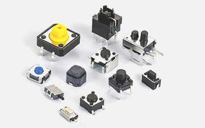
When installing a three speed toggle switch, it is necessary to consider electrical connection reliability, mechanical stability, and operational safety. Improper handling of details may result in poor contact, switch jamming, or equipment failure. The following are key precautions:
1、 Preparation details before installation
Parameter and model verification
Confirm that the rated voltage and current of the switch match the circuit (if the equipment operates at a current of 2A, the rated current of the switch should be ≥ 2A to avoid overload and burnout);
Check the gear logic (such as "0-1-2" or "1-0-2") to ensure consistency with the circuit design (for example, for motor forward and reverse control, it is necessary to confirm that "gear 1" corresponds to forward and "gear 2" corresponds to reverse, to avoid reverse connection).
Appearance and condition inspection
Check whether the switch lever is flexible, and whether there is any jamming or abnormal noise when it is turned (if there is, it may be that the internal contacts are misaligned and need to be replaced);
Check if the pins/pads are oxidized or deformed (oxidized pins need to be lightly sanded to remove rust, and deformed pads need to be corrected before soldering);
Confirm that there are no cracks on the casing (especially on the plastic base, cracks may cause poor insulation).
2、 Details of mechanical fixation
Hole size and positional accuracy
Drill holes on the equipment panel according to the specifications of the switch (such as diameter and length), with a hole diameter error of ≤ 0.1mm (too large may cause the switch to loosen, and too small may cause deformation of the housing due to compression);
The opening position should be horizontal/vertical (according to the installation direction of the switch), and inclined installation will cause uneven force on the lever, shortening its service life.
Fixed method selection
Panel installation (with nut fixation):
After the switch passes through the panel, tighten it with the matching nut (moderate force, too tight will crack the plastic shell, too loose will cause the switch to shake);
If the panel is thin (<1mm), a gasket (metal or hard plastic) can be added on the inside of the panel to prevent the nut from getting stuck in the panel.
PCB board soldering and fixing:
The pins of the direct insertion switch need to be inserted into the corresponding holes on the PCB board, with a length of 2-3mm exposed from the back of the PCB (too long is prone to bending, too short cannot be welded firmly);
SMT switches need to ensure that the solder pads are completely aligned with the PCB solder pads (offset ≤ 0.5mm) to avoid bridge short circuits during soldering.
Avoid external compression
Reserve sufficient space around the switch (at least 5mm greater than the length of the lever) to prevent the device casing or other components from squeezing the lever (causing inability to move or damage to internal contacts);
If the switch is installed in a narrow space (such as inside the instrument), avoid foreign objects such as cables and screws getting stuck in the gap of the lever.
3、 Key details of electrical connections
Welding process control (for direct insertion/surface mount)
Direct insertion switch:
The welding temperature should be controlled at 250-280 ℃, with a time of ≤ 3 seconds per pin (high temperature or exceeding the time limit may cause the plastic base to melt and the pins to oxidize);
Use tweezers to secure the switch during welding to prevent solder from flowing to the moving parts of the lever (causing jamming).
Surface mounted switch:
When using reflow soldering, the peak temperature must meet the temperature resistance requirements of the switch (ordinary model ≤ 260 ℃, high temperature model ≤ 300 ℃);
When manually welding, first weld one pad for positioning, adjust the switch level, and then weld the remaining pads to avoid deformation under stress.
Wire connection (for terminal switches)
The stripping length of the wire is 1-2mm (exposing the core wire that is too short for poor contact and too long for easy short circuit), and the core wire needs to be tightened (multi strand wire needs to be tinned);
After inserting the terminal, tighten the screw (the force should be such that the wire is not loose, over tightening may break the core wire or slide the wire);
Distinguish between the common terminal (COM) and the constant starting point (NO1, NO2), and connect them according to the circuit diagram (for example, connecting "1st gear" to NO1 and "2nd gear" to NO2, incorrect connections can cause confusion in gear function).
Insulation and anti short circuit treatment
After welding, check if there is a solder bridge between the pins. If there is, use a solder suction tape to remove it;
Insulated gaskets (such as barley paper) should be added between the switch and the metal casing, especially in high-voltage circuits to prevent electrical leakage between the pins and the casing;
Wrap the wire connection with heat shrink tubing (or wrap it with insulating tape) to avoid contact and short circuit with other components.
4、 Testing details after installation
Mechanical function testing
Pull the lever to test all gears and confirm that each gear is positioned clearly (with obvious "sticking points"), without any looseness or automatic return phenomenon;
Continuously move the lever 10-20 times and observe if it is smooth without any abnormal noise (if it is stuck, it may be due to deformation of the shell or foreign objects during welding).
Electrical performance testing
Use a multimeter to check the "conduction mode" of each gear: when turned to "mode 1", the common terminal is conductive with NO1 (resistance<10m Ω) and disconnected from NO2 (resistance ∞); When set to "2nd gear", the common terminal is connected to NO2 and disconnected from NO1; Disconnect all switches when set to '0' (ensure logical correctness);
Power on test (low-voltage circuits can be directly powered on, high-voltage circuits need to be powered off first to test conductivity), confirm that the corresponding functions of each gear are normal (such as motor forward and reverse rotation, light switching).
Environmental adaptability verification
If used in humid/dusty environments, check the protective structure after installation (such as whether the waterproof gasket is in place and whether the dust cover is fastened);
Vibration environment (such as on-board equipment) requires secondary reinforcement (such as adding shock-absorbing pads), and after testing, check again whether the switch is loose.
 Haofu ElectronicsFocused on switch/socket/connector manufacturers
Building D, Fuhui Chuangyuan Industrial Park, Dongjiang Road, Huangjiang Town, Dongguan City