The core of using a reset tactile switch revolves around "correct triggering, standardized wiring, and avoiding misoperation and damage". It needs to be combined with its "instantaneous conduction and automatic reset" characteristics to adapt to the installation and operation needs of different scenarios. The following provides a detailed explanation of the usage guidelines for resetting tactile switches, including basic operation methods, wiring and circuit adaptation, and key usage points in different scenarios:

1、 Basic operation method: Master the correct way of "trigger reset"
The operation of resetting the tactile switch relies on "external pressure triggering", and attention should be paid to the force, angle, and frequency to avoid damage or functional failure of the switch due to improper operation:
1. Trigger operation (conducting circuit)
Force application method: Use your fingers (or matching button cap) to vertically press the "button end" of the switch (usually a protruding plastic/metal cap), and the direction of force application should be consistent with the axis of the switch (avoid oblique pressing, prevent internal spring plate displacement or buckle damage).
Force control: The pressure should reach the "rated operating force" of the switch (usually 50-300gf, marked differently for different models, such as 100gf indicating a triggering force of 100 grams), without excessive force (excessive force will accelerate internal spring fatigue and shorten the life) - when triggered, there will be a slight "click" sound and tactile feedback, indicating that the circuit is conductive.
Trigger duration: Control the pressing duration according to the demand (instantaneous pressing: within 1 second, suitable for "reset, confirm" function; long pressing: 3-5 seconds, suitable for "forced restart, mode switching", requires circuit programming implementation), but it should be noted that the switch is designed for "instantaneous contact", and long-term continuous pressing (such as more than 10 minutes) may cause internal spring deformation and inability to reset.
2. Reset operation (disconnect circuit)
No additional operation required: After removing the pressing force, the internal elastic spring of the switch will automatically rebound, restoring the initial open circuit state (reset time is usually less than 10ms, imperceptible to the naked eye), and the circuit will be disconnected accordingly.
Exception handling: If the switch does not reset after the force is removed (the circuit continues to conduct), it is necessary to check whether there are foreign objects (such as dust, debris) stuck between the button and the housing, or if the internal spring has been deformed or damaged (the switch needs to be replaced).
2、 Wiring and circuit adaptation: Ensure "reliable conductivity and normal function"
The reset touch switch needs to be correctly connected to the circuit in order to achieve the function of "pressing to conduct and pulling to disconnect". The wiring method may vary slightly depending on the packaging (plug-in/patch):
1. Preparation before wiring
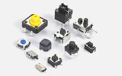
Identifying pins: First, clarify the pin definitions of the switch (commonly 2, 4, and 6 pins, with the core being the "normal start" and "common terminal"):
2-pin switch: with only 2 pins, namely "common terminal (COM)" and "normally open terminal (NO)", the two pins are disconnected in natural state and conduct when pressed;
4-pin/6-pin switches: They are mostly designed with "symmetrical pins" (such as 4-pin switches, where pins 1 and 2 are grouped together and pins 3 and 4 are grouped together, with identical functions), in order to enhance soldering stability. In actual wiring, only one set of "common terminal+normal starting terminal" needs to be connected (without the need for all connections).
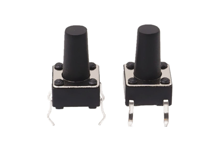
Tools and materials: Prepare tools according to the packaging type - plug-in switches require soldering iron, solder, and wires; Surface mount switches require SMT soldering equipment (such as reflow soldering furnaces, and manual soldering requires micro soldering irons), avoiding the use of high-power soldering irons (such as>60W, which can easily damage the switch housing).
2. Wiring steps (taking plug-in 2-pin switch as an example)
Circuit design: Connect the switch in series in the circuit that needs to be controlled (such as LED indicator light circuit, microcontroller reset circuit). If "anti shake" is required (instantaneous poor contact may occur when pressed, causing circuit flicker), an "RC anti shake circuit" (resistor+capacitor) needs to be added to the circuit or anti shake can be achieved through microcontroller software programming (such as delay detection).
Pin processing: If there is an oxide layer on the switch pin, gently polish it with fine sandpaper (or wipe it with alcohol) to ensure good soldering contact; The plug-in pins should be reserved with a length of 1-2mm to avoid short circuits caused by excessive length or virtual soldering caused by insufficient length.
Welding fixation: Insert the switch pins into the corresponding solder pad holes on the PCB board, dip a small amount of solder with an electric soldering iron (power 30-40W), and quickly solder (solder time for each pin is less than 3 seconds to avoid high temperature damage to the internal spring). After soldering, check for virtual soldering or short circuits (measure with a multimeter on/off mode, the two pins are disconnected in natural state, and conduct when pressed).
Attention to SMT switches: When manually soldering SMT switches, it is necessary to first fix one pin, adjust the switch position to align it with the solder pad, and then solder the other pin to avoid pulling the pin forcefully, which may cause the switch to shift or be damaged.
3. Circuit protection
Avoid overcurrent: Design the circuit according to the "rated current" of the switch (usually 100mA-500mA, and high-power models can reach 1A). If the circuit current exceeds the rated value, a current limiting resistor or relay should be connected in series (such as a 1k Ω resistor in the LED circuit to avoid burning out the switch contacts due to excessive current).
Anti reverse connection: Some switches do not have positive or negative poles (only mechanical contacts), but if there are polarity components (such as diodes or transistors) in the circuit, it is necessary to ensure that the switch wiring does not affect the circuit polarity to avoid component damage.
3、 Key points for use in different scenarios: Adapt to device requirements and avoid functional failure
The reset touch switch is widely used for the "reset, confirm, trigger" functions of electronic devices. Different scenarios require targeted attention to operation and installation details:
1. Consumer electronics scenarios (such as mobile phones, remote controls, smart bracelets)
Installation requirements: Micro patch switches (size < 5mm × 5mm) are commonly used in this type of equipment. During installation, it is necessary to ensure that the switch is aligned with the housing buttons (deviation ≤ 0.1mm) to avoid the switch being inaccessible when the button is pressed, or only pressing the edge of the switch causing damage to the spring plate.
Operation precautions: If the device shell buttons have dust film or silicone cover, it is necessary to ensure that the force can be effectively transmitted to the switch when pressed (excessive thickness of the silicone cover may cause insensitive triggering); Avoid using sharp objects (such as nails or pen tips) to directly press the switch (without casing protection) to prevent the button cap from breaking.
Typical functions: phone reset button (long press for 10 seconds to force restart), remote control confirmation button (instant press to trigger command), smart wristband function switch button (short press to switch mode, long press to enter settings).
2. Industrial control scenarios (such as machine tool control panels, PLC reset buttons)
Installation requirements: Industrial equipment often uses reset touch switches with waterproof and dustproof enclosures (protection level IP65/IP67). During installation, the fixing screws of the enclosure need to be tightened to ensure that the sealing ring is in place (to prevent oil and dust from entering the interior of the switch and causing poor contact); The switch should be fixed on the metal panel to avoid loosening caused by equipment vibration.
Operation precautions: In industrial scenarios, switches are often combined with "emergency stop, reset" functions. When pressing, confirm the operation intention (such as ensuring that the equipment is in a safe state before resetting the machine tool) to avoid equipment failure caused by misoperation; If there is oil pollution in the environment, regularly wipe the surface of the switch with alcohol to prevent oil from infiltrating the interior and affecting the elasticity of the spring.
Typical functions: Machine tool emergency stop reset (press to release the emergency stop state), PLC program reset (instantaneous press to clear fault codes).
3. Smart home scenarios (such as smart speakers, floor cleaning robots)
Installation requirements: Smart home devices are mostly made of plastic shells. When installing switches, a buffer pad (such as a silicone pad) should be added between the shell and the switch to avoid accidental triggering of the switch due to vibration during device operation; If the device needs to be wall mounted, the switch position should be easy for the user to press (height 1.2-1.5m, avoid being too high or too low).
Operation precautions: The reset switch of some devices is hidden at the bottom or side of the device (such as in a small hole), and should be gently pressed with tools such as toothpicks or fine needles (force ≤ 100gf) to avoid excessive force causing the switch pins to break; After triggering, wait for the device to respond (such as the indicator light flashing) and confirm that the reset is successful.
Typical functions: Restore the smart speaker to factory settings (long press for 5 seconds), trigger partial cleaning of the robotic vacuum cleaner (short press to start).
 Haofu ElectronicsFocused on switch/socket/connector manufacturers
Building D, Fuhui Chuangyuan Industrial Park, Dongjiang Road, Huangjiang Town, Dongguan City